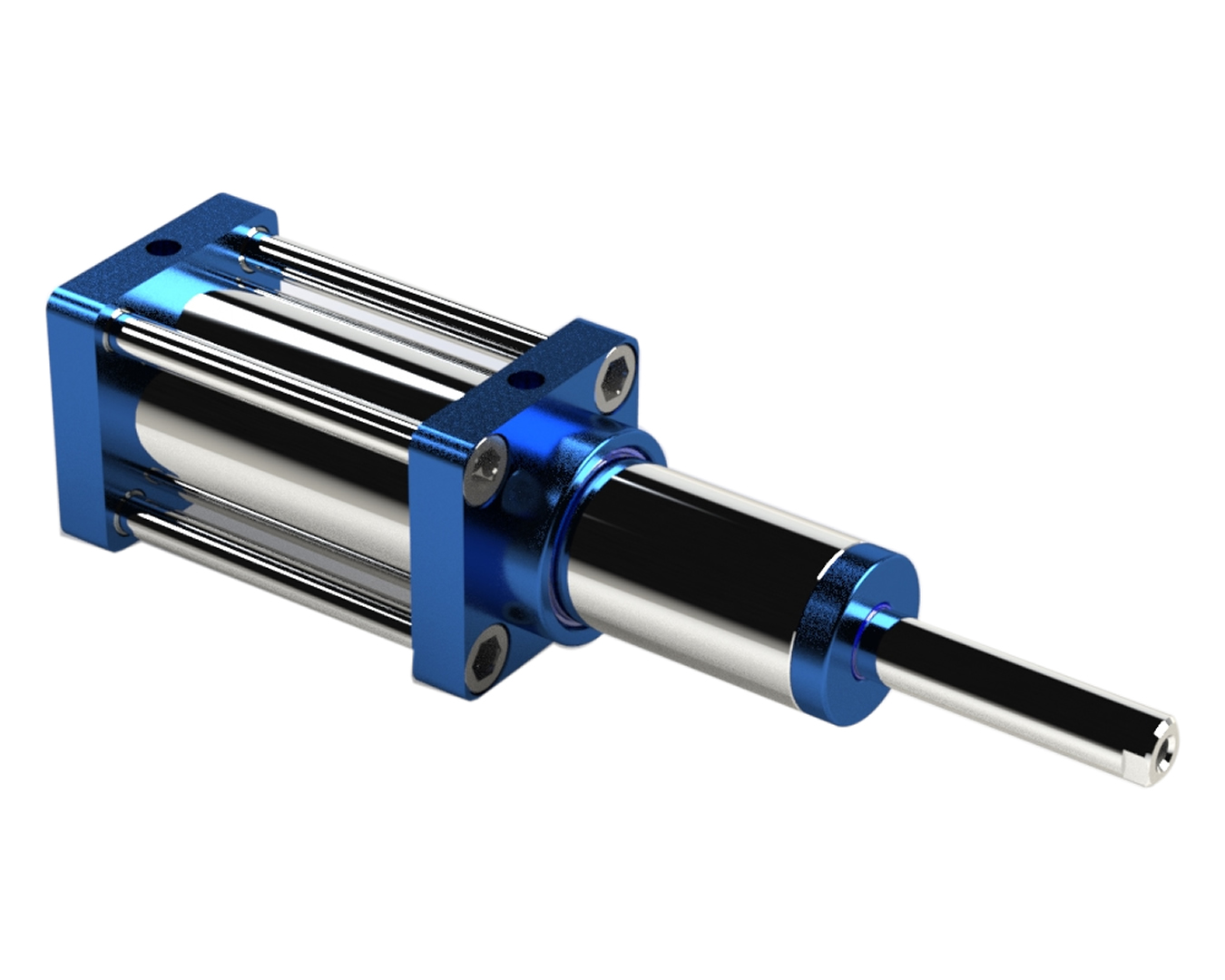
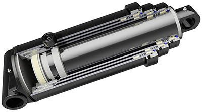
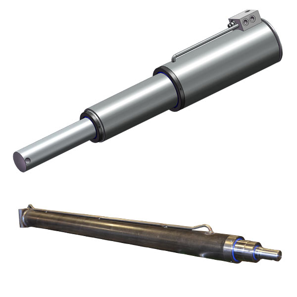
Product Description
Product Description
| Bore of cylinder's first stage | Stroke | Upper mouting | Upper mouting | Mounting dimension | Working pressure | ||
| Diameter of the hole | Deep | Diameter of the hole | Deep | ||||
| 5 | 84.00 | 1.63 | 1.50 | 2.00 | 7.00 | 41.09 | 2500 |
| 6 | 120.06 | 2.00 | 2.00 | 2.00 | 7.00 | 52.62 | 2500 |
| 7 | 120.00 | 2.00 | 2.00 | 2.00 | 8.25 | 53.12 | 2500 |
| 8.125 | 234.00 | 2.00 | 2.00 | 2.00 | 9.50 | 64.62 | 2500 |
| 9.375 | 235.00 | 2.00 | 2.00 | 2.00 | 10.88 | 65.44 | 2500 |
| L2 | L3 | L4 | L5 | L6 | ØA | Fitting | Workable container length | Rear suspension length | Lift angle | Lift capacity | Oil tank volume |
| 65 | 360 | 60 | 325 | 1585 | Ø60 | G1 | 4700-5300 | 800 | 47-52° | 43 | 80 |
| 65 | 360 | 60 | 325 | 1270 | Ø60 | G1 | 4700-5300 | 800 | 47-52° | 31 | 80 |
| 65 | 360 | 60 | 325 | 1390 | Ø60 | G1 | 5300-6000 | 800 | 47-52° | 36 | 80 |
| 65 | 360 | 60 | 325 | 1510 | Ø60 | G1 | 5800-6500 | 800 | 47-52° | 36 | 80 |
| 65 | 360 | 60 | 325 | 1385 | Ø60 | G1 | 5300-5800 | 800 | 47-52° | 53 | 80 |
| 65 | 360 | 60 | 325 | 1505 | Ø60 | G1 | 5800-6500 | 800 | 47-52° | 53 | 100 |
| 65 | 360 | 60 | 325 | 1580 | Ø60 | G1 | 6200-6800 | 800 | 47-52° | 58 | 100 |
| 65 | 360 | 60 | 325 | 1655 | Ø60 | G1 | 6600-7200 | 800 | 47-52° | 58 | 100 |
| 65 | 360 | 60 | 325 | 1125 | Ø60 | G1 | 5000-5500 | 800 | 47-52° | 46 | 80 |
| 65 | 360 | 60 | 325 | 1165 | Ø60 | G1 | 5300-6000 | 800 | 47-52° | 46 | 80 |
| 65 | 360 | 60 | 325 | 1265 | Ø60 | G1 | 5800-6500 | 800 | 47-52° | 49 | 80 |
| 65 | 360 | 60 | 325 | 1340 | Ø60 | G1 | 6200-6800 | 800 | 47-52° | 49 | 80 |
| 65 | 360 | 60 | 325 | 1385 | Ø60 | G1 | 6600-7200 | 800 | 47-52° | 49 | 80 |
| 65 | 360 | 65 | 325 | 1455 | Ø60 | G1 | 5600-6300 | 800 | 47-52° | 66 | 120 |
| 65 | 360 | 65 | 325 | 1505 | Ø60 | G1 | 5800-6500 | 800 | 47-52° | 66 | 120 |
| 65 | 360 | 65 | 325 | 1580 | Ø60 | G1 | 6200-6800 | 800 | 47-52° | 70 | 120 |
| 65 | 360 | 65 | 325 | 1655 | Ø60 | G1 | 6600-7200 | 800 | 47-52° | 70 | 120 |
| 65 | 360 | 65 | 325 | 1750 | Ø60 | G1 | 7200-8000 | 1000 | 47-52° | 70 | 135 |
| 65 | 360 | 65 | 325 | 1270 | Ø60 | G1 | 7200-8000 | 1000 | 47-52° | 49 | 120 |
| 65 | 360 | 65 | 325 | 1675 | Ø65 | G1 | 6600-7200 | 800 | 47-52° | 92 | 165 |
| 65 | 360 | 65 | 325 | 1770 | Ø65 | G1 | 7200-8000 | 1000 | 47-52° | 96 | 165 |
| 65 | 360 | 65 | 325 | 1870 | Ø65 | G1 | 8000-8500 | 1000 | 47-52° | 96 | 185 |
| 65 | 360 | 65 | 325 | 1770 | Ø65 | G1 | 8700-9500 | 1000 | 47-52° | 88 | 185 |
Company Profile
Certifications
Packaging & Shipping
FAQ
Q1: Can your cylinders with HYVA ones ?
Yes, our cylinders can replace HYVA ones well, with same technical details and mounting sizes
Q2: What's your cylinder's advantages ?
The cylinders are made under strictly quality control processing.
All the raw materials and seals we used are all from world famous companies.
Cost effective
Q3: When your company be established ?
Our company be established in 1996, and we are professional for hydraulic cylinders for more than 25 years.
And we had passed IATF 16949:2016 Quality control system.
Q4: How about the delivery time ?
For samples about 20 days. And 15 to 30 days about mass orders.
Q5: How about the cylinder's quality gurantee ?
We have 1 year quality grantee of the cylinders.
| Certification: | ISO9001, IATF 16949:2016 |
|---|---|
| Pressure: | High Pressure |
| Work Temperature: | Normal Temperature |
| Acting Way: | Double Acting |
| Working Method: | Straight Trip |
| Adjusted Form: | Regulated Type |
| Samples: |
US$ 1000/Piece
1 Piece(Min.Order) | |
|---|
| Customization: |
Available
|
|
|---|

How do telescopic cylinders handle variations in load capacity and weight?
Telescopic cylinders are designed to handle variations in load capacity and weight effectively. Here's a detailed explanation:
Load-specific design:
Telescopic cylinders are engineered with load-specific design considerations to accommodate variations in load capacity and weight. Manufacturers take into account factors such as the maximum expected load, the range of anticipated loads, and the required safety factors. The cylinder's components, materials, and dimensions are selected and configured accordingly to provide the necessary strength and stability.
Multiple stages:
The nested structure of telescopic cylinders, with multiple stages or sleeves that retract inside one another, allows for adaptability to different loads. Each stage can handle a specific portion of the load, and the collective capacity of all stages determines the overall load capacity of the cylinder. By adding or removing stages, telescopic cylinders can be customized to suit different load requirements, providing flexibility in handling variations in weight.
Hydraulic system control:
The hydraulic control system of telescopic cylinders plays a vital role in managing variations in load capacity. By regulating the flow of hydraulic fluid to each stage, operators can control the extension and retraction force applied to the cylinder. This control allows for adjustments based on the specific load and weight requirements, ensuring the cylinder operates within its safe working limits.
Pressure relief and overload protection:
Telescopic cylinders are often equipped with pressure relief valves and overload protection mechanisms to safeguard against excessive loads. Pressure relief valves help prevent over-pressurization of the hydraulic system by diverting excess fluid flow, protecting the cylinder from potential damage. Overload protection mechanisms, such as overload sensors or mechanical stops, are designed to activate and halt the cylinder's movement if the load exceeds the safe operating limits.
Load distribution and stability:
Telescopic cylinders contribute to load distribution and stability. The nested design distributes the load across multiple stages, reducing stress on individual components and enhancing overall stability. Proper weight distribution on the machinery or equipment, as well as secure attachment of the load, further contribute to maintaining stability and ensuring safe operation.
It's important to note that while telescopic cylinders can handle variations in load capacity and weight, it is crucial to operate within the specified load limits and follow the manufacturer's guidelines. Exceeding the recommended load capacity can compromise the safety, performance, and longevity of the telescopic cylinder and the machinery it is installed on.
Consulting the manufacturer's documentation, engineering specifications, and relevant industry standards is essential for understanding and adhering to the appropriate load capacity and weight guidelines when using telescopic cylinders.

How do telescopic cylinders contribute to precise reach and manipulation?
Telescopic cylinders play a crucial role in enabling precise reach and manipulation in various applications. Here's a detailed explanation:
Extended reach:
Telescopic cylinders allow for extended reach in equipment such as cranes, excavators, booms, and material handling machinery. The nested design of telescopic cylinders, with multiple stages that retract inside one another, enables the equipment to achieve a longer reach when required. By extending the telescopic cylinder, operators can access objects or work areas that are located at a distance.
Precise positioning:
Telescopic cylinders provide precise positioning capabilities, allowing operators to manipulate objects with accuracy. The hydraulic control system regulates the extension and retraction of each stage of the cylinder, enabling smooth and controlled movement. This precise control is essential in applications that require accurate placement or manipulation of objects, such as in construction, manufacturing, or material handling.
Load handling:
Telescopic cylinders contribute to precise load handling by providing the necessary force and control. The cylinders are designed to handle heavy loads and can exert the required power to lift, lower, or manipulate objects with precision. The hydraulic control system allows operators to adjust the speed and movement of the telescopic cylinder, ensuring safe and controlled load handling.
Adaptability:
Telescopic cylinders offer adaptability in reaching and manipulating objects in various environments. Their nested design allows for compact retraction, making them suitable for applications with limited space. The ability to extend and retract the telescopic cylinder provides flexibility in adjusting the reach and adapting to different working conditions.
Support for attachments:
Telescopic cylinders often support attachments or tools that enhance reach and manipulation capabilities. For example, in excavators, telescopic cylinders are used to extend the boom or arm, while additional attachments such as buckets or grabs facilitate precise material handling or excavation tasks.
Overall, telescopic cylinders contribute to precise reach and manipulation by offering extended reach, precise positioning, load handling capabilities, adaptability, and support for attachments. Their hydraulic control system and nested design enable operators to achieve accurate and controlled movements, enhancing productivity and efficiency in various applications.
It's important to consult the equipment manufacturer's documentation and guidelines for specific information on the telescopic cylinder's capabilities, operating parameters, and recommended maintenance practices to ensure optimal performance and safety.

What are the components and design features of a telescopic cylinder?
A telescopic cylinder consists of various components and incorporates specific design features to enable its functionality and performance. Here's a detailed explanation:
Components of a telescopic cylinder:
- Stages or Sleeves: A telescopic cylinder comprises multiple stages or sleeves that are nested inside one another. These stages are usually cylindrical in shape and are made of high-strength steel or aluminum alloy. The number of stages can vary depending on the specific design and application requirements.
- Piston and Rod: Each stage of a telescopic cylinder has its own piston and rod assembly. The piston is located inside the stage and is connected to the rod, which extends through the center of the stage. The piston and rod assembly is responsible for generating the linear motion of each stage during extension and retraction.
- Seals: Sealing elements, such as O-rings or lip seals, are used to ensure a hydraulic seal between the stages. These seals prevent leakage of hydraulic fluid and maintain pressure within each stage during operation. The seals also help to protect the internal components from contaminants.
- Locking Mechanism: Telescopic cylinders often incorporate a locking mechanism to secure the extended stages in position. This mechanism ensures stability and prevents unintentional retraction of the cylinder under load. The locking mechanism can be mechanical, hydraulic, or a combination of both, depending on the design and application requirements.
- Guides and Bearings: To maintain proper alignment and minimize friction between the stages, telescopic cylinders may include guides and bearings. These components facilitate smooth extension and retraction of the stages and provide structural support.
- Hydraulic Connections: Telescopic cylinders have hydraulic connections to supply hydraulic fluid for extension and retraction. These connections typically include ports or fittings for the inlet and outlet of hydraulic fluid. Flexible hydraulic hoses or tubing are used to connect the cylinder to the hydraulic system of the equipment.
Design features of a telescopic cylinder:
- Nested Structure: The nested structure is a fundamental design feature of a telescopic cylinder. It allows the stages to extend and retract within one another, enabling a longer stroke length while maintaining a compact retracted length.
- Articulation Capability: Some telescopic cylinders incorporate articulation capability, which allows the cylinder to adjust its angle or position relative to the equipment. This feature enhances the versatility of the cylinder and enables it to adapt to different mounting orientations and working conditions.
- Internal Flow Paths: The design of a telescopic cylinder includes internal flow paths that facilitate the controlled flow of hydraulic fluid between the stages during extension and retraction. These flow paths ensure synchronized movement of the stages and contribute to the overall performance and stability of the cylinder.
- Surface Treatment: The external surfaces of telescopic cylinders are often treated or coated to provide protection against corrosion, wear, and environmental elements. Common surface treatments include painting, powder coating, or electroplating.
These components and design features work together to enable the functionality, reliability, and performance of a telescopic cylinder. It's important to consult the manufacturer's guidelines and specifications for proper installation, operation, and maintenance of the telescopic cylinder based on the specific application requirements.


editor by CX 2023-11-17